Physical Address
Lahore, Punjab, Pakistan
Physical Address
Lahore, Punjab, Pakistan


Comprehensive preparation guide for E&I engineers, automation technicians, and instrumentation professionals — from fundamentals to advanced concepts.
A Programmable Logic Controller (PLC) is a ruggedized industrial digital computer designed to control manufacturing processes, machinery, or any industrial activity that requires high reliability, ease of programming, and process fault diagnosis.
PLCs were invented in the late 1960s to replace relay-based control panels in automotive manufacturing. Unlike general-purpose computers, PLCs are built to withstand harsh industrial environments — extreme temperatures, vibration, electrical noise, and humidity.
A PLC system consists of several key hardware components:
The Scan Cycle is the repetitive sequence of operations a PLC performs continuously during normal operation. It consists of four phases:
The IEC 61131-3 standard defines five programming languages for PLCs:
| Language | Type | Best Used For |
|---|---|---|
| Ladder Diagram (LD) | Graphical | Discrete logic, relay replacement, familiar to electricians |
| Function Block Diagram (FBD) | Graphical | Process control, signal flow (PID, analog) |
| Structured Text (ST) | Textual | Complex algorithms, math, string operations |
| Instruction List (IL) | Textual | Low-level, assembly-like (now deprecated in IEC 61131-3 Ed.3) |
| Sequential Function Chart (SFC) | Graphical | Sequential processes, state machines, batch control |
Ladder Diagram (LD) is a graphical programming language that resembles electrical relay logic diagrams. Each “rung” of the ladder represents a control logic statement — power flows from the left power rail through contacts (conditions) to a coil or output on the right.
It is widely used because:
—[ ]— = NO contact, —[/]— = NC contact, —( )— = output coil.| Property | Normally Open (NO) | Normally Closed (NC) |
|---|---|---|
| Default State | Open (no current flow) | Closed (current flows) |
| When bit = 1 | Closes (allows current) | Opens (blocks current) |
| Ladder Symbol | —[ ]— | —[/]— |
| Physical Example | Pushbutton START | E-Stop, overload relay |
| Logic | EXAMINE IF CLOSED (XIC) | EXAMINE IF OPEN (XIO) |
Important: These are software contacts in the PLC program. A physical NC device (like an E-Stop) can be programmed as a NO contact if its physical state is inverted — always align your program logic with physical wiring and fail-safe principles.
An Output Coil (symbol: —( )—) is placed at the right end of a rung and is energized (set to 1) when all conditions to its left provide a continuous logic path (rung is TRUE). When the rung goes FALSE, the coil de-energizes (resets to 0).
Types of output coils:
Physical Output: Directly maps to an output terminal on the PLC I/O module. When energized, it activates a real-world device (relay, valve, lamp, motor contactor).
Internal/Memory Coil (Marker Bit): A software bit stored in the PLC memory with no physical connection. Used to create internal logic flags, intermediate results, and to avoid double-coil issues.
B3 file or BOOL tags are internal bitsM-Memory (Merker) bits are used (M0.0, M0.1…)%M bits are internal memory coilsA Timer instruction in PLC measures elapsed time and activates an output after a defined time period.
| Timer Type | Full Name | Behavior |
|---|---|---|
| TON | Timer ON-Delay | Output turns ON after preset time when input is TRUE. Resets immediately when input goes FALSE. |
| TOF | Timer OFF-Delay | Output turns OFF after preset time when input goes FALSE. Output turns ON immediately when input is TRUE. |
| RTO | Retentive Timer ON | Accumulates time even when input goes FALSE. Requires an explicit RES (Reset) instruction to clear accumulated value. |
Key parameters: Preset (PT) — target time value. Elapsed Time (ET/ACC) — current count. IN/EN — enable input bit. Q/DN — done bit (output).
A Counter instruction counts events (rising edges of a signal) and activates an output when the count reaches the preset value.
| Counter | Name | Function |
|---|---|---|
| CTU | Count Up | Increments accumulator on each rising edge of CU input. Done (Q/CU) bit sets when ACC ≥ Preset. |
| CTD | Count Down | Decrements accumulator on each rising edge of CD input. Done (Q) bit sets when ACC ≤ 0. |
| CTUD | Count Up/Down | Can count both up and down. QU sets when ACC ≥ Preset; QD sets when ACC ≤ 0. |
Use cases: batch counting (bottles filled), production counting, revolution counting, floor selection in elevator control.
| Data Type | Size | Range | Use Case |
|---|---|---|---|
| BOOL | 1 bit | 0 or 1 | Digital I/O, flags, status bits |
| BYTE | 8 bits | 0–255 | Small unsigned integers, packed bits |
| INT | 16 bits | –32,768 to 32,767 | Small whole numbers, analog raw values |
| DINT | 32 bits | –2,147,483,648 to 2,147,483,647 | Large counters, position values |
| REAL | 32 bits (IEEE 754) | ±1.18×10⁻³⁸ to ±3.4×10³⁸ | Floating-point: flow rates, temperatures, PID outputs |
| STRING | Variable | Character arrays | Operator messages, serial communication |
| TIME | 32 bits | Duration in ms | Timer preset and elapsed values |
SET (S / OTL — Output Latch): When the rung condition goes TRUE, the output bit is set to 1 and remains 1 even if the rung goes FALSE. It retains its state until explicitly reset.
RESET (R / OTU — Output Unlatch): When the rung condition goes TRUE, it clears (sets to 0) the bit that was previously latched by a SET instruction.
Common applications:
Modern PLC platforms (especially Allen-Bradley ControlLogix/CompactLogix) use a tag-based addressing model:
Tag: A named variable directly associated with a memory location. Tags are typed (BOOL, INT, REAL, UDT) and organized in Controller or Program scope. Example: Motor_01_Running, Tank_Level_PV.
Older fixed-address systems (like SLC-500 or Siemens S5) used Symbols: a descriptive alias mapped to a fixed memory address like N7:0 or I0.0.
The MOVE (MOV) instruction copies the value from a source to a destination when the rung is TRUE. It is one of the most fundamental data manipulation instructions in PLC programming.
Common uses:
Example (ST): Tank_Setpoint := 75.0; — equivalent to MOV 75.0 → Tank_Setpoint.
| Property | Retentive Memory | Non-Retentive Memory |
|---|---|---|
| On Power Loss | Retains last value (backed by battery/NVRAM) | Resets to 0 or default on power cycle |
| Use Case | Production counters, recipe parameters, alarm history | Standard BOOL flags, intermediate variables |
| AB ControlLogix | Tag marked “Retain” | Standard tags |
| Siemens S7 | DB with retentive attribute, M-Memory range | Standard M-Memory bits |
| Timer Type | RTO (Retentive Timer ON) | TON, TOF |
Function Block Diagram (FBD) is a graphical IEC 61131-3 language where interconnected function blocks represent program flow. Data flows left-to-right between block pins (inputs/outputs), resembling a signal flow diagram.
FBD is preferred for:
Key blocks: PID, SCALE, LIM, ADD, MUL, SWITCH, AND, OR. Each block has standard input/output pins and can be instantiated multiple times with different parameters.
Structured Text (ST) is a high-level, Pascal-like textual programming language defined in IEC 61131-3. It supports loops, conditionals, functions, and complex expressions.
Syntax example:
IF Tank_Level > 90.0 THEN Inlet_Valve := FALSE; ELSIF Tank_Level < 20.0 THEN Inlet_Valve := TRUE; END_IF;
Advantages:
FOR, WHILE, REPEAT) for array processing and recipesSequential Function Chart (SFC) is a graphical IEC 61131-3 language used to structure sequential programs as a state machine. It is derived from the French Grafcet standard (IEC 60848).
Key elements:
SFC is ideal for: batch processes, filling machines, washing cycles, automated assembly sequences.
A PID (Proportional-Integral-Derivative) Controller is a closed-loop control algorithm that automatically adjusts a process output to maintain a measured variable (Process Variable / PV) at a desired setpoint (SP).
The control output is: CV = Kp×e + Ki×∫e dt + Kd×de/dt where e = SP – PV (error)
PLC Implementation: Use the built-in PID function block (e.g., PID_AW in Siemens, PIDE in AB ControlLogix). Configure: PV input (analog tag), SP (setpoint), CV output (analog output tag), Kp, Ti, Td, output limits, and deadband.
Common applications: Temperature control, pressure regulation, level control, flow control.
| Property | Digital I/O | Analog I/O |
|---|---|---|
| Signal Type | Discrete ON/OFF (0V or 24V DC) | Continuous (4–20mA, 0–10V, ±10V) |
| PLC Data | BOOL (1 bit) | INT/REAL (12–16 bit resolution) |
| Devices Connected | Pushbuttons, limit switches, solenoids, pilot lights | Transmitters (PT, TT, FT), control valves, VFDs |
| Scaling Required | No | Yes (raw counts → engineering units) |
| Example Signal | Motor Run Feedback (ON/OFF) | Tank Level: 4mA=0%, 20mA=100% |
| Property | Function (FC / Fun) | Function Block (FB) |
|---|---|---|
| Internal State | Stateless — no memory between calls | Stateful — retains values between scans |
| Instance Data | No instance required | Requires an instance (separate data block per instance) |
| Return Value | Returns a single value | No direct return value; outputs via output variables |
| Use Case | Mathematical calculations, conversions | PID loops, motor control, valve sequencing |
| Reusability | Called with different inputs each time | Each instance maintains its own state independently |
Example: A MotorStarter FB with inputs (Start, Stop, Fault) and outputs (Run, Alarm) can be instantiated for Motor_01, Motor_02, Motor_03 — each maintaining its own run state independently.
A Watchdog Timer (WDT) is a hardware/software timer that monitors the PLC scan cycle. At the end of each successful scan, the CPU resets this timer. If the scan takes longer than the watchdog preset (typically 100–500 ms), the watchdog expires and forces the PLC into a FAULT state, safely de-energizing outputs.
Why it’s critical:
SCADA (Supervisory Control and Data Acquisition) is a software system used to monitor, visualize, and control industrial processes from a central location. It provides real-time data, historical trending, alarm management, and reporting.
SCADA–PLC interface methods:
SCADA reads PLC tags for display and writes setpoints/commands back to PLC. The PLC remains in control of real-time execution; SCADA is supervisory only.
| Aspect | PLC | DCS |
|---|---|---|
| Full Form | Programmable Logic Controller | Distributed Control System |
| Architecture | Centralized or small distributed | Fully distributed, redundant controllers |
| Primary Use | Discrete manufacturing, machine control | Continuous process control (oil & gas, chemical, power) |
| Programming | Ladder, ST, FBD (IEC 61131-3) | FBD, SFC, vendor-specific tools |
| Scan Time | 1–100 ms (fast discrete) | 100 ms–1s (process loop based) |
| HMI/SCADA | External SCADA/HMI required | Integrated engineering and operator workstations |
| Examples | AB ControlLogix, Siemens S7, Schneider M340 | Honeywell Experion, ABB 800xA, Emerson DeltaV |
Modern boundaries are blurring — high-end PLCs with distributed I/O and integrated HMI increasingly compete with DCS in process industries.
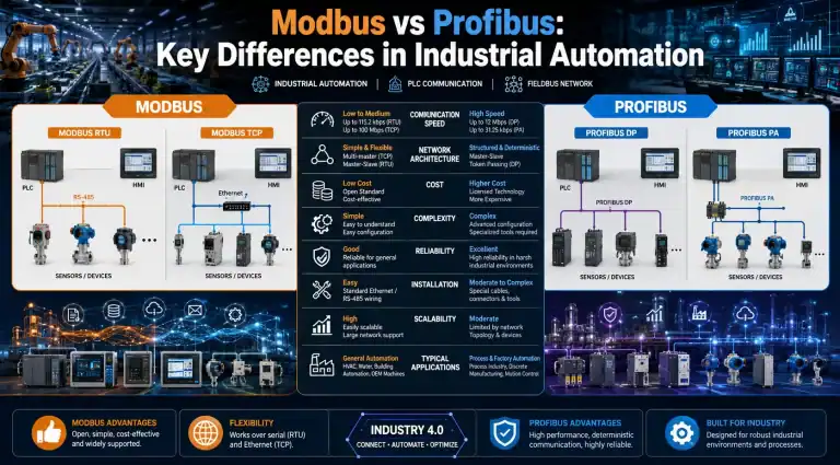
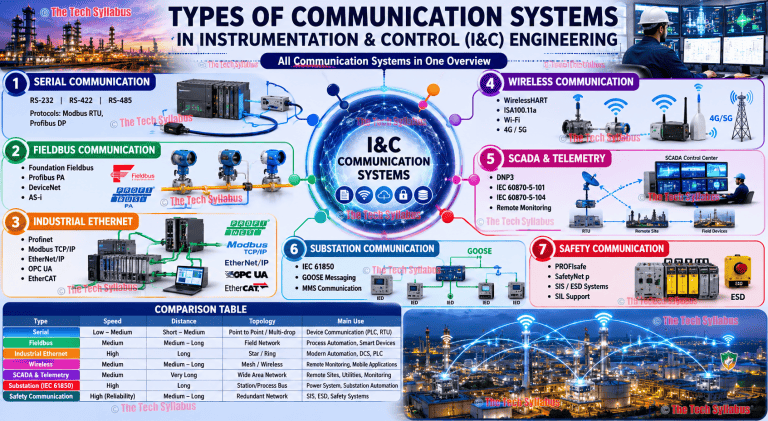
Modbus is a serial/Ethernet communication protocol developed by Modicon in 1979. It is one of the most widely used industrial communication protocols due to its simplicity and open standard.
Variants:
Modbus data model — four register types:
0x (Coils): Read/write BOOL outputs1x (Discrete Inputs): Read-only BOOL inputs3x (Input Registers): Read-only 16-bit analog values4x (Holding Registers): Read/write 16-bit values (most used)Common use: PLC communicating with VFDs, energy meters, weighing controllers, flow computers, and third-party instruments.
EtherNet/IP (Ethernet Industrial Protocol) is an industrial Ethernet protocol developed by Rockwell Automation and managed by ODVA. It uses standard Ethernet hardware (Cat5e/Cat6, TCP/IP, UDP/IP) but adds the CIP (Common Industrial Protocol) application layer on top.
Unlike office Ethernet, EtherNet/IP uses managed switches with QoS prioritization, separate network segments, and defined update rates to ensure determinism. It is native to Allen-Bradley ControlLogix/CompactLogix systems and supported by many third-party devices.
An HMI (Human-Machine Interface) is a touchscreen or panel display that allows operators to monitor process variables, issue commands, acknowledge alarms, and adjust setpoints — without writing PLC code.
Communication methods:
HMI designers create graphical screens with PLC tag bindings. Tags are polled or subscribed based on the protocol. Trend displays sample values periodically. Alarm servers monitor PLC bits and timestamps events.
Edge detection instructions detect the transition of a signal rather than its steady state. They are active for only one scan cycle:
Typical applications:
Indirect Addressing (also called indexed or pointer-based addressing) allows a PLC to access an array element using a variable index rather than a fixed address. The index value itself can change at runtime.
Example in ST: Motor_Status[RecipeStep] — where RecipeStep is a runtime variable selecting which array element to access.
Common applications:
In Allen-Bradley ControlLogix/CompactLogix (Studio 5000):
| Property | Controller Scope Tags | Program Scope Tags |
|---|---|---|
| Visibility | Accessible by ALL programs in the controller | Accessible ONLY within the program that owns them |
| Best For | Global data shared across programs: I/O tags, shared setpoints, system status | Local variables: internal flags, counters, timers, temp values |
| Memory | Shared memory space | Isolated per program |
| HMI Access | Directly accessible | Must be promoted to controller scope or accessed with full path |
Online Editing allows engineers to modify a PLC program while the controller is in RUN mode — without stopping the machine. Changes are staged in a pending edit buffer and then accepted into the running program.
Precautions:
FIFO (First In, First Out): Data is queued like a pipeline — the first value entered is the first one retrieved. Think of it as a conveyor belt buffer.
LIFO (Last In, First Out): Data is stacked — the last value entered is the first one retrieved. Think of it as a stack of plates.
| Property | FIFO | LIFO |
|---|---|---|
| Data Order | Oldest first out | Newest first out |
| PLC Instructions | FFL (Load) / FFU (Unload) | LFL (Load) / LFU (Unload) |
| Application | Product tracking (serial number queue), ordered batch processing | Nested subroutine returns, temporary storage reversal |
Example FIFO use: A conveyor with 10 positions — each product’s serial number is loaded as it enters; as products exit, serial numbers are unloaded in the same entry order for printing labels.
Interrupt Routines are special program routines that execute in response to a specific event, pausing the main scan cycle to run immediately. They are not executed in the normal rung-by-rung scan order.
Types of interrupts:
A User-Defined Data Type (UDT) — called a Structure in IEC 61131-3 — is a custom composite data type that groups multiple elements of different types under a single named tag.
Example UDT for a pump:
Pump_UDT.Start_CMD : BOOLPump_UDT.Run_FB : BOOLPump_UDT.Fault : BOOLPump_UDT.Speed_SP : REALPump_UDT.Runtime_Hours : DINTBenefits:
A 4–20 mA signal from a transmitter is converted by the analog input module into a raw integer count (typically 0–32767 or 0–4095 depending on module resolution).
Scaling formula:
EU = (Raw – Raw_Min) / (Raw_Max – Raw_Min) × (EU_Max – EU_Min) + EU_Min
Example: Pressure transmitter, 0–100 bar, module range 0–32767:
PLC implementations:
SCL instruction or CPT with the formulaFC105 (SCALE) or NORM_X + SCALE_X in TIA PortalA Safety PLC (also called a Safety Controller or SIS controller) is a special PLC certified to execute Safety Instrumented Functions (SIFs) up to a defined Safety Integrity Level (SIL) per IEC 61508/IEC 61511.
| Property | Standard PLC | Safety PLC |
|---|---|---|
| Standard | IEC 61131-3 | IEC 61508 / IEC 61511 / IEC 62061 |
| Architecture | Simplex or hot-standby | 1oo2, 2oo3 voting (diverse redundancy) |
| Self-Diagnostics | Basic watchdog only | Continuous self-test of CPU, memory, I/O |
| Programming | Standard IEC languages | Safety-certified subset of IEC languages |
| Fail-Safe Action | Not always guaranteed | Always drives to defined safe state on any failure |
| Examples | AB ControlLogix, Siemens S7-300 | AB GuardLogix, Siemens S7-300F/400F, Hima HIMAX |
Safety PLCs use certified software development processes, separate safety and standard task execution, and require SIL verification calculations (SFF, PFD, PFH) and FMEA studies.
| Property | PROFIBUS DP/PA | PROFINET |
|---|---|---|
| Medium | RS-485 (DP) / MBP (PA) | Ethernet (Cat5e/Cat6) |
| Speed | Up to 12 Mbit/s (DP) | 100 Mbit/s – 1 Gbit/s |
| Topology | Bus (daisy-chain) | Star, ring, bus (switched Ethernet) |
| Max Devices | 126 per segment | 255+ per controller |
| PA Support | Yes (intrinsically safe, process instruments) | Via PROFIBUS PA proxy |
| Real-Time Class | RT (cyclic) | RT, IRT (isochronous, <1ms jitter) |
| Integration | GSD files | GSDML files |
PROFIBUS is the older established serial standard widely used in process industries. PROFINET is the modern Ethernet-based successor, offering higher speed, standard IT infrastructure compatibility, and Isochronous Real-Time (IRT) capability for motion control applications.
OPC-UA (OPC Unified Architecture) is a platform-independent, service-oriented industrial communication protocol developed by the OPC Foundation. It provides secure, reliable, manufacturer-independent data exchange from the sensor level to the cloud.
Key features:
In Industry 4.0, OPC-UA serves as the standard bridge between OT (Operational Technology) and IT layers — PLCs expose OPC-UA servers, and MES/ERP/cloud platforms act as clients, enabling real-time production data analytics without custom middleware.
PLC Redundancy is a system architecture where duplicate components operate in parallel to ensure continuous operation if one component fails. Required for critical processes where downtime costs are extremely high.
Redundancy types:
Motion Control in PLC refers to precise control of servo motors, stepper motors, and linear actuators for positioning, speed, and coordinated multi-axis movement. Governed by PLCopen Motion Control function blocks (Part 1: Single Axis).
Key function blocks:
MC_Power: Enable/disable the drive axisMC_Home: Execute homing sequence to establish absolute position referenceMC_MoveAbsolute: Move to an absolute position at defined velocity/accelerationMC_MoveRelative: Move a defined distance from current positionMC_MoveVelocity: Run at constant velocity (conveyor, winding)MC_GearIn: Electronic gearing between axes (follower tracks master)MC_CamIn: Electronic cam profile (custom motion curve per revolution)Platforms: AB Kinetix (Studio 5000), Siemens S7 with S120/SINAMICS, Beckhoff TwinCAT NC.
A structured troubleshooting approach:
The MSG (Message) instruction in Allen-Bradley ControlLogix/CompactLogix initiates asynchronous, explicit data exchanges between two devices over a network. Unlike implicit I/O (which runs cyclically), MSG is triggered on demand.
MSG can be configured for:
Best practice: Trigger MSG with a one-shot (OSR) instruction to avoid re-triggering each scan. Check MSG.EN (enabled), MSG.DN (done), MSG.ER (error) and MSG.ERR code for diagnostics.
| Aspect | Allen-Bradley (Rockwell) | Siemens | Schneider Electric |
|---|---|---|---|
| Top Platform | ControlLogix L8x | SIMATIC S7-1500 | Modicon M580 |
| Software | Studio 5000 / RSLogix | TIA Portal / STEP 7 | EcoStruxure Control Expert (Unity Pro) |
| Network | EtherNet/IP (CIP native) | PROFINET/PROFIBUS native | EtherNet/IP + Modbus TCP |
| Addressing | Tag-based (named variables) | Symbolic (TIA) / Address-based (Classic) | Tag-based |
| Market Strength | Americas, F&B, automotive | Europe, Asia, process industry | Europe, energy, water, mining |
| Safety | GuardLogix | S7-300F/400F/1500F | Modicon M580 Safety |
Distributed I/O (also called Remote I/O) places I/O modules physically close to field devices rather than running all wiring back to a central panel. An I/O adapter at each remote location communicates with the main PLC over a fieldbus.
Architecture:
Benefits: Drastically reduces home-run cable costs on large plants, easier maintenance, faster troubleshooting, modular expansion. Widely used in power plants, refineries, and large water treatment facilities.
IEC 61131-3 is the international standard for PLC programming languages, published by the International Electrotechnical Commission. It is Part 3 of the broader IEC 61131 series covering PLC hardware, communication, and guidelines.
Significance:
Industrial Control System (ICS) cybersecurity protects PLCs, SCADA, and HMI systems from cyber threats. Standards: IEC 62443 (Industrial Automation and Control System Security), NIST CSF.
Key threats to PLC systems:
Best practices:
A Soft PLC runs IEC 61131-3 control programs on a standard industrial PC (IPC) under a real-time OS, replacing dedicated PLC hardware. The runtime environment (e.g., CODESYS, Beckhoff TwinCAT) provides the PLC execution engine.
| Property | Hardware PLC | Soft PLC (PC-based) |
|---|---|---|
| Processor | Dedicated embedded CPU | Standard Intel/ARM processor |
| OS | RTOS baked in firmware | Real-time OS (TwinCAT, CODESYS RTE, INtime) |
| I/O Coupling | Backplane bus (fast) | EtherCAT, EtherNet/IP, PROFINET fieldbus |
| Performance | Deterministic, proven, simple | Can achieve sub-millisecond cycle with EtherCAT IRT |
| Cost | Higher for high-channel-count | Lower hardware cost, higher software cost |
| Example | AB ControlLogix | Beckhoff CX series + TwinCAT |
Soft PLCs dominate in robotics, packaging machines, and motion-intensive applications where high-performance computing is needed alongside control.
In a Combined Cycle Power Plant (CCPP), PLCs typically handle balance-of-plant (BOP) and auxiliary system control, while the main gas turbine and steam turbine control is handled by vendor-specific TMR (Triple Modular Redundant) controllers (e.g., GE Mark VIe, Siemens T3000).
Typical PLC responsibilities in CCPP:
IIoT (Industrial Internet of Things) integration connects PLCs and field devices to cloud platforms for real-time analytics, predictive maintenance, digital twin, and enterprise dashboards.
Implementation architectures:
Use cases: Equipment runtime analytics, OEE (Overall Equipment Effectiveness) calculation, predictive maintenance alerts, production KPI dashboards on tablets.
Professional PLC programs require structured documentation for long-term maintainability, safe modifications, and regulatory compliance.
Program Documentation:
PMP-101_Start_CMD)Version Control:
No questions match your search.