Physical Address
Lahore, Punjab, Pakistan
Physical Address
Lahore, Punjab, Pakistan

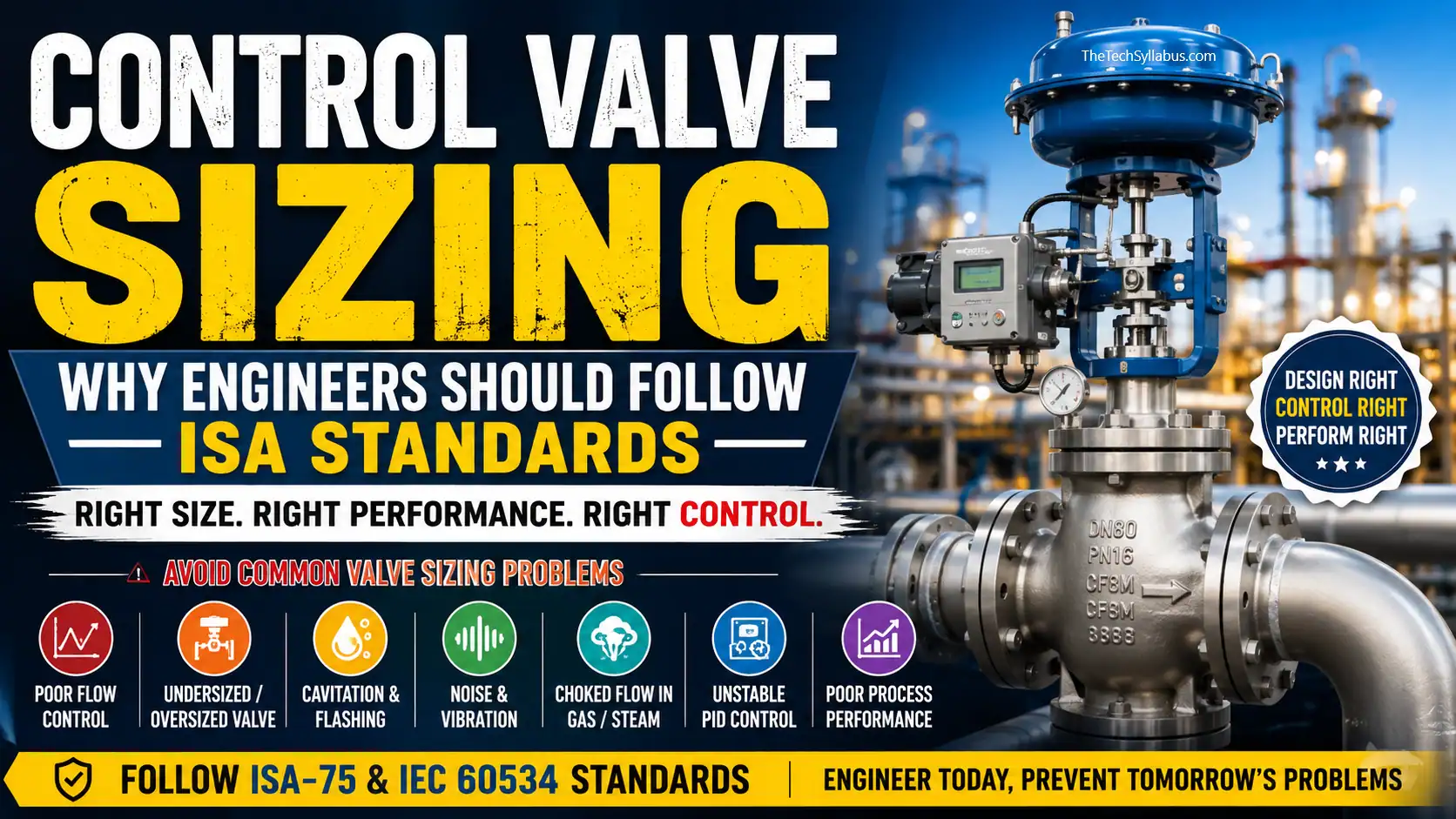
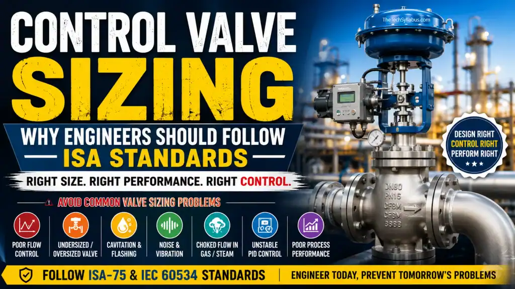
During site visits, I often come across a very common but critical problem:
The control valve is installed, the actuator is working, the positioner is calibrated, and the DCS output is healthy, but the required process flow is still not being properly controlled.
At first, the problem is often blamed on:
But sometimes the real problem is much simpler:
The control valve was not properly sized in the first place.
This is not merely a commissioning problem.
It is an engineering design problem.
And this is exactly why engineers should follow recognized control-valve sizing practices such as the ISA-75 series and IEC 60534 rather than selecting a valve simply because it matches the pipeline size or is readily available from a vendor. ISA states that its ISA-75 series provides guidance covering control-valve design, sizing, selection, testing, and performance.
One of the most common mistakes is:
“The line is 8 inches, therefore the control valve should also be 8 inches.”
This is not a valid sizing methodology.
A control valve must be selected based on the required flow capacity and actual process conditions, not simply the nominal pipe diameter.
The sizing calculation should consider:
Follow ANSI/ISA-75.01.01 / IEC 60534-2-1 for control-valve flow-capacity sizing.
This standard provides sizing equations for both compressible and incompressible fluids under installed conditions.
An undersized valve may be physically installed and fully functional, but it simply does not have enough capacity.
For example:
Required maximum flow = 100 t/h
But the selected valve can only provide the required flow when operating at or near its maximum capacity.
The valve may remain:
90% → 95% → 100% OPEN
while the process still cannot achieve the required flow.
Recalculate the valve according to ANSI/ISA-75.01.01 / IEC 60534-2-1.
Do not accept a valve merely because its nominal size matches the line.
Verify the calculated Cv/Kv at minimum, normal, and maximum flow conditions.
Oversizing is another serious problem.
Suppose the process requires a relatively small flow, but an unnecessarily large valve is selected.
The valve may operate around:
5% → 10% → 15% OPEN
for normal process operation.
Now a very small change in valve position can cause a large change in flow.
The result can be:
Small signal change → Large flow change → Overshoot → Controller correction → Hunting
Use the applicable ISA-75 sizing and flow-characteristic guidance and evaluate the valve’s operating range rather than looking only at the maximum Cv.
ANSI/ISA-75.11.01 provides standardized guidance for inherent flow characteristics and rangeability of control valves.
The engineer should verify the valve travel at:
A valve that provides excellent maximum capacity but operates in an extremely small travel range during normal operation is not necessarily a good control-valve selection.
This is one of the most common arguments in commissioning.
The operator says:
“Flow is fluctuating.”
The control engineer says:
“PID needs tuning.”
The instrument engineer adjusts the PID.
Again, the flow fluctuates.
The PID is adjusted again.
Still the same problem.
At this point, engineers should ask:
Is the control valve correctly sized and behaving properly?
A control loop cannot be expected to perform well if the final control element has inappropriate installed gain or operating range.
Before continuously changing PID parameters:
Check the control valve sizing, installed characteristics, travel, position stability, and response.
ISA-75 includes guidance related to valve position stability and control-valve response/performance evaluation.
For liquid services, incorrect valve sizing can result in excessive pressure recovery and local pressure falling below vapor pressure.
This can produce:
Cavitation
Typical consequences include:
For applicable liquid services, perform the required cavitation assessment using the relevant ISA-75 guidance, including ISA-RP75.23, Considerations for Evaluating Control Valve Cavitation. ISA currently lists this document in its ISA-75 series.
Do not wait until the valve starts making abnormal noise at site.
Cavitation should be evaluated during engineering design.
Flashing is different from cavitation.
If the liquid pressure falls below vapor pressure and the vapor remains present downstream, continuous flashing can occur.
This can cause severe erosion and damage to the valve and downstream piping.
Perform the required hydraulic assessment during valve sizing using the applicable ISA/IEC control-valve sizing methodology.
The engineer should evaluate:
P1 → Valve → P2 → Vapor pressure
before finalizing the valve and trim selection.
Gas and steam services require additional attention.
A valve may reach a condition where increasing the pressure differential no longer produces the expected increase in flow.
This is known as choked flow.
It can be accompanied by:
For compressible-flow services, perform the appropriate ISA-75.01.01 / IEC 60534-2-1 sizing calculation and verify the applicable critical/choked-flow conditions.
Do not size steam or gas control valves using a simple liquid Cv calculation.
Sometimes the valve is controlling, but the noise level is unacceptable.
This can occur particularly in:
Perform the appropriate control-valve noise assessment using the applicable ISA-75 noise guidance, including ISA-75.07 for aerodynamic noise prediction and laboratory measurement references in the ISA-75 series.
The objective is not only:
“Will the valve pass the flow?”
The question should also be:
“Will the valve pass the flow reliably, controllably and within acceptable noise limits?”
Another problem occurs when the valve’s inherent characteristic is not suitable for the process.
Common characteristics include:
Selecting the wrong characteristic can adversely affect the installed control response.
Evaluate the required valve characteristic and rangeability using the applicable ANSI/ISA-75.11.01 guidance. ISA identifies this standard specifically for inherent flow characteristics and rangeability of control valves.
The valve characteristic should be selected based on the actual process dynamics—not simply vendor preference.
Sometimes the valve itself has been selected correctly, but the actuator cannot reliably overcome the required forces.
This can result in:
Actuator sizing should be properly evaluated using the applicable ISA-75.24 control-valve actuator sizing and selection guidance.
ISA identifies ISA75.24 specifically for determining the forces acting on valve closure components and the parameters affecting actuator sizing.
Another engineering shortcut is:
“Vendor has this valve available, so let’s use it.”
This approach can create problems later.
A valve should be selected because it satisfies the process requirement, not because it is available in the vendor’s stock.
Prepare and approve a proper Control Valve Sizing Calculation before final valve selection.
The vendor should then select a valve that satisfies the approved process sizing requirements.
Vendor selection should follow engineering requirements rather than replace them.
A valve may look perfect when checked only at normal flow.
But what happens at:
Minimum flow?
Normal flow?
Maximum flow?
This is where many problems become visible.
For every critical control valve, verify the selected valve for all relevant design/operating cases using the applicable ANSI/ISA-75.01.01 / IEC 60534-2-1 sizing methodology.
A proper valve sizing sheet should clearly demonstrate that the valve can handle the required operating envelope.
Before approving a control valve, ask these questions:
What are the minimum, normal, and maximum flows?
What are P1, P2 and ΔP for each operating case?
What is the calculated Cv/Kv?
At what valve opening will the valve operate at minimum, normal, and maximum flow?
Has cavitation/flashing been checked?
Has choked flow been checked?
Has noise been evaluated?
Is linear or equal-percentage characteristic appropriate?
Has the actuator been properly sized for the worst-case condition?
Which ISA/IEC standard was used for the sizing calculation?
If these questions cannot be answered, the valve should not simply be approved because the vendor has submitted a datasheet.
We need to move away from:
“The valve is installed, let’s see if it works.”
And move toward:
“The valve has been mathematically and technically verified before it reaches site.”
That is the purpose of engineering standards.
Standards are not paperwork.
They are a way of preventing expensive mistakes.
The ISA-75 series covers much more than basic valve sizing.
ISA identifies its ISA-75 standards as covering control-valve selection, sizing, testing and application, with additional guidance on characteristics, actuator sizing, noise, cavitation, diagnostics and performance.
Some particularly relevant references include:
| Engineering Concern | Relevant ISA Guidance |
|---|---|
| Flow capacity/sizing | ANSI/ISA-75.01.01 / IEC 60534-2-1 |
| Capacity testing | ANSI/ISA-75.02.01 |
| Valve terminology | ANSI/ISA-75.05.01 |
| Flow characteristic & rangeability | ANSI/ISA-75.11.01 |
| Aerodynamic noise | ISA-75.17 / ISA-75.07 |
| Cavitation | ISA-RP75.23 |
| Actuator sizing | ISA-75.24 / applicable ISA technical guidance |
| Position stability | ISA-TR75.04.01 |
| Valve response | ANSI/ISA-75.25.01 |
| Valve diagnostics | ANSI/ISA-75.26.01 |
ISA’s official standards listing confirms these documents as part of the ISA-75 control-valve standards family.
As engineers, we should not wait for the site to tell us that our design is wrong.
If a control valve is:
the first question should be:
“Was the valve properly engineered and sized according to the applicable ISA/IEC methodology?”
Not:
“Can we fix it by changing the PID?”
A control valve is not simply a pipeline valve with an actuator.
It is the final control element of the process control loop.
Its sizing directly affects:
Flow → Pressure → Process Stability → PID Performance → Equipment Reliability → Plant Production
Therefore, control valve engineering should never be based on:
❌ Pipe size only
❌ Vendor availability
❌ Previous project practice
❌ Guesswork
❌ “Same size as the line”
❌ PID tuning after installation
Instead, it should be based on:
✅ Actual process data
✅ Minimum / Normal / Maximum conditions
✅ Cv/Kv calculation
✅ Valve travel evaluation
✅ ISA/IEC sizing methodology
✅ Cavitation/flashing assessment
✅ Choked-flow assessment
✅ Noise evaluation
✅ Proper valve characteristic
✅ Proper actuator sizing
✅ Vendor calculation verification
Engineers should follow ISA standards not because a standard exists, but because the consequences of not following it eventually appear at site.
A control valve that looks correct on a drawing can become one of the biggest process-control problems during commissioning if it was not properly sized.
So before approving the next control valve, ask one simple question:
“Show me the ISA/IEC-based sizing calculation.”
If we make that question a standard part of engineering review, many of the control problems we currently discover at site can be prevented during design.
Design it correctly.
Size it correctly.
Verify it against ISA/IEC.
Then take it to site.
Q1. What is control valve sizing?
Control valve sizing is the engineering process of determining the appropriate valve capacity, typically expressed using Cv or Kv, based on process flow, pressure, temperature, and fluid properties.
Q2. Why is control valve sizing important?
Proper sizing ensures the valve can control minimum, normal, and maximum process flow while avoiding problems such as poor controllability, excessive pressure drop, cavitation, flashing, and noise.
Q3. What standard is used for control valve sizing?
ANSI/ISA-75.01.01 and IEC 60534-2-1 are key standards used for control-valve flow-capacity sizing.
Q4. Should a control valve be the same size as the pipeline?
Not necessarily. Control valve size should be determined from process conditions and required flow capacity rather than pipe size alone.
Q5. Can PID tuning fix an incorrectly sized control valve?
PID tuning cannot fully compensate for an improperly sized control valve. The valve’s capacity and operating range should first be verified.