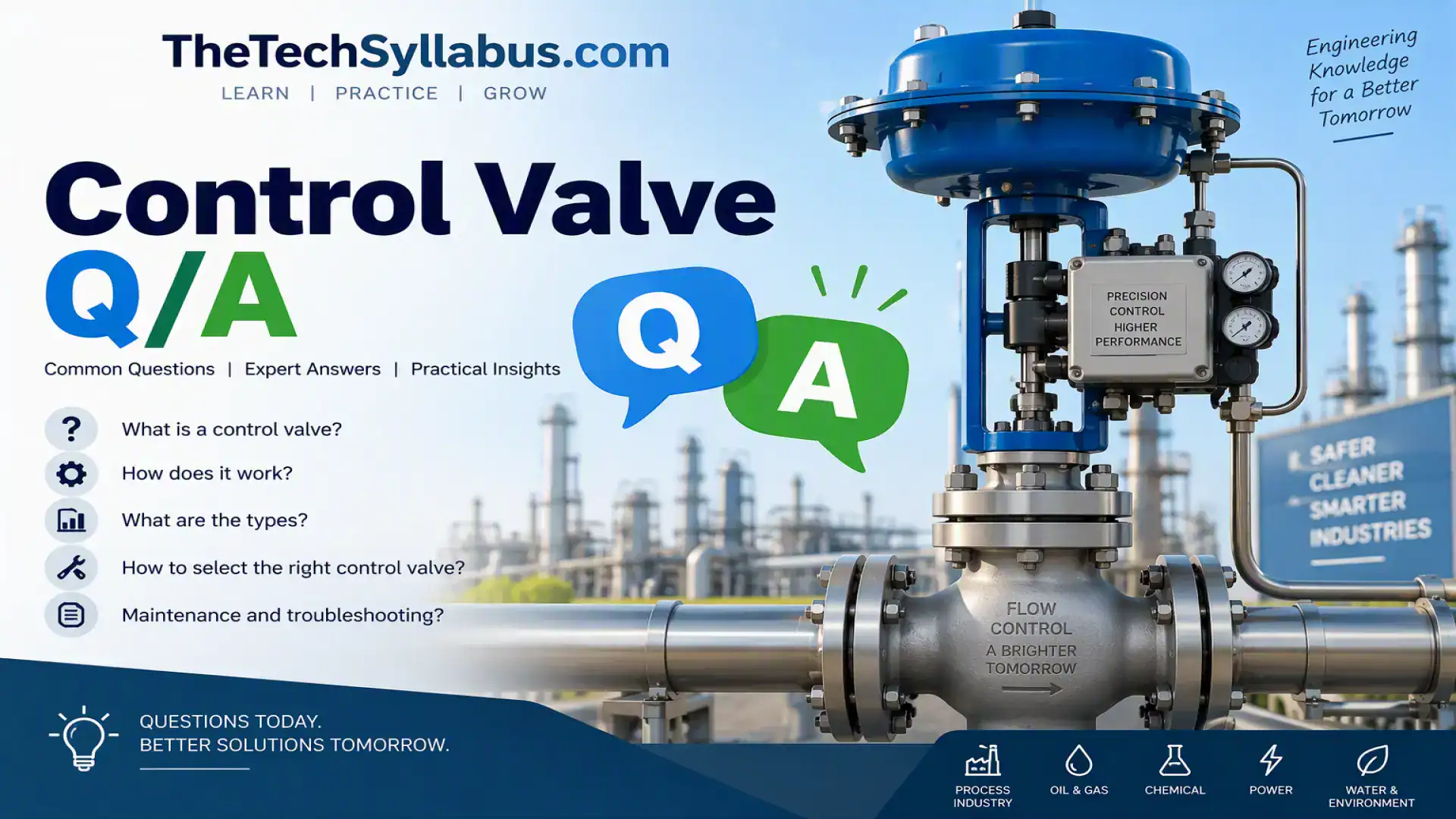
From basic concept to sizing, tuning, cascade and ratio loops. Simple English, practical examples, made for E&I engineers and students in Pakistan.
1. Introduction to Control Valves
Basic concept, types, flow and cavitation.
Q1. What is a control valve and why do we use it?
A control valve is the "final control element" in a loop. It changes the opening of the pipe passage, so the flow of liquid, gas or steam goes up or down. Because of this, we can control pressure, flow, level or temperature.
Simple example: In a boiler, the level transmitter tells the controller that drum level is low. The controller sends a 4-20 mA signal, and the feed water control valve opens more. Level comes back to set point.
A control valve has three main parts: the body (with trim), the actuator (gives motion) and the positioner (makes sure the valve reaches the exact position).
Q2. How are control valves classified? What are the common types?
We can classify them by stem motion:
Linear motion (sliding stem): globe valve, diaphragm valve, gate valve.
Accurate throttling, high pressure drop, steam and feed water
Butterfly
Large lines, low pressure drop, cooling water, air
Ball (V-notch)
Slurry, fibre, good rangeability
Diaphragm
Corrosive or dirty fluid, low pressure
Gate
Mostly on/off isolation, not for throttling
Q3. What are actuators and positioners? How do they work?
The actuator moves the valve stem. Pneumatic (air) actuators are most common in plants. Electric and hydraulic actuators are also used.
Spring-diaphragm: simple, reliable, spring gives fail-safe action.
Piston: for high thrust, long stroke or high pressure.
The positioner compares the 4-20 mA command with actual stem position and adjusts air pressure until both match. Without positioner, friction and process force can make the valve inaccurate.
Fail action: Air-to-open means valve closes on air failure (fail-close). Air-to-close means it opens on air failure (fail-open). Select this by process safety, not by habit.
Q4. What are the types of flow inside a control valve?
Laminar flow: smooth, layered, happens at low velocity or high viscosity.
Turbulent flow: mixed and chaotic, most common in process lines. Sizing formulas mostly assume this.
Choked flow: flow stops increasing even if downstream pressure falls more. In liquids it happens due to vapour formation (vena contracta). In gas it happens when velocity reaches sonic.
If valve is choked, increasing pressure drop will not give more flow. It will only give more noise and damage.
Q5. What are cavitation and flashing? Why are they dangerous?
Inside the valve, liquid speed becomes very high at the narrowest point (vena contracta) and pressure drops. If this pressure goes below vapour pressure, bubbles form.
Flashing: downstream pressure also stays below vapour pressure, so bubbles remain. The liquid becomes a mixture of vapour and liquid. Damage looks smooth and polished (erosion).
Cavitation: downstream pressure recovers above vapour pressure, so bubbles collapse violently. This gives noise like gravel in pipe, vibration and pitted, rough trim surface.
Solutions: anti-cavitation trim, multi-stage pressure drop, harder trim material (stellite), or install valve where downstream pressure is higher.
2. Valve Characteristics and Specifications
Flow characteristics, P&ID, leakage, installation and hand calculation.
Q6. What is valve inherent flow characteristic?
It is the relation between valve opening (% travel) and flow, when pressure drop across the valve is kept constant.
Type
Behaviour
Typical use
Linear
Flow changes equally with travel
Level control, constant pressure drop
Equal percentage
Each step gives same % change in flow
Pressure and temperature loops, changing pressure drop
Quick opening
Large flow at small opening
On/off, relief type service
In real plant, pump and piping change the pressure drop, so the installed characteristic differs from inherent one. Equal percentage often becomes close to linear after installation.
Q7. How do we choose a valve for different operating conditions?
Clean liquid, high ΔP: globe valve with proper trim.
Steam, high temperature: globe valve, check material (e.g. alloy steel) and pressure class.
Slurry or sticky fluid: V-notch ball or eccentric plug.
Big pipe, low pressure drop: butterfly valve.
Tight shut-off required: choose seat type and leakage class first.
Always collect data first: fluid, flow (min/normal/max), inlet and outlet pressure, temperature, vapour pressure, viscosity and line size.
Q8. How are valves shown in a P&ID?
On the P&ID (as per ISA S5.1 symbols), a control valve is shown as a body symbol with an actuator symbol on top. Look for these items:
Valve tag, for example FV-101 (F = flow, V = valve).
Fail action arrow or letters: FO, FC, FL (fail last).
Signal line (dashed) from controller, such as FIC-101.
Isolation valves, bypass valve and drain around the control valve.
Line size and valve size if different.
Q9. What is valve leakage and what are the leakage classes?
Leakage is the flow passing through the valve when it is fully closed. Standard is ANSI/FCI 70-2 (also IEC 60534-4).
Class
Meaning
II
0.5% of rated capacity (general service)
III
0.1% of rated capacity
IV
0.01%, most common for metal seat control valves
V
Very tight, tested with water
VI
Bubble-tight, soft seat
A control valve is not a shut-off valve. If process needs zero leakage, add a separate isolation valve.
Q10. What are the important points for valve installation?
Keep valve in accessible place, with space to remove actuator and trim.
Install block valves on both sides and one bypass line for maintenance.
Follow flow direction arrow on body.
Provide straight pipe run before and after (as per vendor recommendation).
Install valve in horizontal pipe with actuator vertical on top, if possible.
Flush the line before installing, so welding slag does not damage trim.
Support heavy actuators properly and keep air supply clean and dry.
Q11. How do we do a manual valve sizing calculation?
Valve flow coefficient Cv is the water flow in US gpm that passes through valve with 1 psi pressure drop. For liquid in turbulent flow:
Cv = Q × √(SG / ΔP)
Q = flow (gpm), SG = specific gravity, ΔP = pressure drop (psi).
Choose valve so that normal flow is around 60 to 70% opening and max flow below 90%.
Check cavitation, flashing, noise and velocity.
For gas and steam, use the IEC 60534 equation with expansion factor.
Do not add big safety factors. An oversized valve works only 10 to 20% open and controls badly.
3. Maintenance, Sizing and Safety
Specifications, software, SIS valves, noise and safe maintenance.
Q12. What should be written in a control valve specification (datasheet)?
Tag number, service, P&ID number.
Process data: fluid, flow, pressures, temperature, SG or density, viscosity, vapour pressure.
Valve data: type, size, pressure rating, end connection, body and trim material, flow characteristic, leakage class.
Actuator data: type, fail action, air supply pressure, handwheel if required.
Accessories: positioner (HART), air filter regulator, limit switches, solenoid.
Calculated Cv, noise level and travel at min, normal and max.
Q13. Which software is used for valve sizing?
Most vendors give free sizing software, for example Emerson Fisher Specification Manager, Masoneilan (Baker Hughes) and Samson. They calculate Cv, travel, cavitation index and noise from your process data.
The engineer must still check input data, units and results. Also keep a hand calculation as cross-check. Software is a tool, it does not replace engineering judgement.
Q14. How do SIS valves relate to pressure relief?
A SIS (Safety Instrumented System) valve is an on/off valve (shutdown valve) that moves to safe position when a trip happens. It is an active layer of protection, used to stop the hazard before pressure becomes dangerous.
A pressure relief valve (PSV) is the last mechanical layer. It opens by itself when pressure reaches set value.
SIS valve is selected with required SIL (as per IEC 61511).
Check fail-safe action, closing time and leakage.
Do periodic proof test or partial stroke test.
Do not use normal control valve as SIS valve, keep them separate.
Q15. How do we control cavitation and noise?
Multi-stage trim: drop pressure in small steps.
Anti-cavitation trim: special cages that keep pressure above vapour pressure.
Diffusers and silencers: for noisy gas and steam service.
Lower velocity: use bigger valve or pipe expander if needed.
Noise is calculated as per IEC 60534-8. A common design target is below 85 dBA at 1 metre.
Q16. What are the main points of installation, maintenance and safety?
Follow lock-out/tag-out (LOTO), isolate and depressurise the line, then drain it.
Check for hot, toxic or corrosive fluid and wear proper PPE.
Do routine checks: stem leakage, packing, air leaks, positioner calibration.
Do stroke test and check full travel against 4, 12 and 20 mA.
Replace worn trim and seats before leakage becomes big.
Keep records and spare parts for critical valves.
Spring-loaded actuators store energy. Release the spring carefully before opening the actuator.
4. Control Valves in Process Control
Feedback loop, tuning methods and PID controller.
Q17. What are the main features of a process control loop?
PV (process variable): measured value, from transmitter.
SP (set point): value we want.
Error: SP minus PV.
OP (output): controller signal that moves control valve.
Controller reads error, calculates output, and the valve changes flow. The sensor measures again and the loop repeats. This is called a feedback loop.
Q18. What is a PID controller?
P (proportional): output proportional to current error. Gives fast action but leaves some offset.
I (integral): adds up error over time and removes the offset. Too much gives oscillation.
D (derivative): reacts to speed of change, reduces overshoot. Sensitive to noise, so used mostly in temperature loops.
Typical starting use: flow and pressure loops use PI, temperature loops often use PID, level loops often use P or PI.
Q19. What are the types of tuning: open loop and closed loop?
Open loop tuning: controller is in manual. We give a small step change in output and record how PV responds (process reaction curve). From delay time, time constant and gain, we calculate PID values (Ziegler-Nichols or Cohen-Coon methods).
Closed loop tuning: controller stays in auto. We increase gain until loop oscillates steadily. We note ultimate gain (Ku) and ultimate period (Pu), then calculate settings (Ziegler-Nichols ultimate method).
Closed loop method pushes the process to oscillation, so do not use it on critical or dangerous loops.
Q20. How does trial and error tuning work?
Put controller in manual and stabilise the process. Turn off integral and derivative.
Switch to auto with low gain. Make a small set point change.
Increase gain step by step until response is fast but slightly oscillating, then reduce a little.
Add integral action slowly until offset goes away without big oscillation.
Add small derivative only if overshoot is high.
Test again with set point and load changes.
Always change one setting at a time and wait for the process to settle. Be patient, slow processes need more time.
5. Cascade, Ratio and PLC
Advanced control features and valve response.
Q21. What is a cascade loop and where is it used?
Cascade uses two controllers. The primary (master) controller controls the main variable, and its output becomes the set point of the secondary (slave) controller, which acts on the control valve.
Example: Temperature (primary) cascaded to steam flow (secondary). If steam pressure changes, the flow controller corrects immediately, before temperature is disturbed.
Secondary loop must be faster than primary loop.
Tune secondary first, then primary.
Use anti-windup and proper mode tracking.
Q22. What is a ratio loop?
Ratio control keeps one flow in fixed proportion to another "wild" flow. The wild flow is measured, multiplied by a ratio, and the result becomes set point for the second flow controller.
Example: Air to fuel ratio in a boiler burner. If fuel flow goes up, air flow set point also goes up by the set ratio, so combustion stays safe and efficient.
Ratio can be adjusted by operator or by a trim controller (for example, oxygen trim).
Q23. How do we use one valve with multiple controllers?
Sometimes two controllers can affect one valve, for example normal pressure control and a limit control. We use selectors (high, low select) in the DCS/PLC so only one controller drives the valve at a time. This is called override or split-range control (when one controller drives two valves).
Always add anti-windup in the controller not selected, otherwise it will jump when it takes over.
Q24. What affects control valve response, and how does PLC fit in?
Stroke time: how fast valve moves. Slow actuators make the loop slow.
Deadband and stiction: valve does not move for small signal changes, causing limit cycles.
Hysteresis: position differs when moving up and down.
Positioner and air supply: poor air supply slows response.
PLC role: The PLC (or DCS) scans inputs, runs PID blocks, and sends 4-20 mA or HART/fieldbus signal to the positioner. Keep scan time short (for example 100 to 250 ms for fast flow loops), scale the analog signals correctly, and keep valve position feedback in the PLC for diagnostics and alarms.
Quick advice: Always size from real process data, check cavitation and noise, select correct fail action, and tune loops slowly. If you have a question, write in the comments and we will answer. Also visit our free IEC calculators on TheTechSyllabus.com.