Physical Address
Lahore, Punjab, Pakistan
Physical Address
Lahore, Punjab, Pakistan

Focused on system design, equipment sizing, protection coordination, and standards application — the real challenges faced by electrical design engineers in EPC, industrial, and consulting roles.
Load estimation starts with collecting process/mechanical equipment lists with their ratings. Then:
| Factor | Definition | Application |
|---|---|---|
| Demand Factor | Ratio of maximum demand to total connected load | Used to size feeders and service entrance |
| Diversity Factor | Ratio of sum of individual peak loads to system peak load | Reduces transformer/switchgear size |
| Coincidence Factor | 1 / Diversity Factor | Used in LV panel design |
Proper application avoids oversizing equipment and reduces capital cost.
Sum all loads in kVA after applying demand and diversity factors. Include largest motor starting and harmonic contributions. Select next standard size from IEC 60076 or IEEE C57.12.
Consider loading not exceeding 80% for continuous operation and provision for N+1 redundancy if required.
This classification drives the distribution topology and emergency supply sizing.
Historically, the LV distribution in many countries (India, UK, Middle East) used 415V phase-phase (240V phase-neutral). With IEC harmonization, the nominal voltage is now 400V (±6%). Motors rated at 415V can safely operate at 400V with slight derating. Design must check motor terminal voltage under starting conditions.
Key design steps:
A load curve plots the power demand over 24 hours. It helps identify peak demand, average loading, and duration of peaks. Transformers can be loaded beyond rated capacity for short periods based on the thermal time constant (IEC 60076-7). This allows economical sizing, avoiding oversizing for a short peak.
Consider:
Key factors: total emergency kVA, largest motor starting kVA (and voltage dip limitations), load profile (step loading), permissible frequency/voltage dips (ISO 8528). The generator kVA rating must be higher than the maximum load considering starting transients and altitute/temperature derating. Use manufacturer sizing software.
Select based on application per ISO 8528-1.
Vector group describes the phase displacement between primary and secondary windings. Dyn11 (delta-star, 30° lag) is standard for distribution: allows third harmonic circulation in delta, and provides neutral for LV loads. Yyn0 (star-star) has limited zero-sequence current capability and may cause neutral instability with unbalanced loads, so rarely used for distribution. Dyn11 also blocks zero-sequence from HV to LV.
Transformer impedance (%Z) directly limits short-circuit current: I_sc = (100 / %Z) × I_rated. Higher %Z reduces fault level but increases voltage regulation (drop under load). Typical distribution transformers: 4–6%. For parallel operation, %Z must be equal within tolerance to ensure load sharing.
NER limits single-line-to-ground fault current to protect the generator winding. Typical limitation: 10A–25A for low-resistance grounding. Calculated as R = V_LN / I_fault. Must withstand the fault current for a defined time (typically 10 sec). Coordinate with protection settings (59N, 51G).
Inrush current (up to 10–15× FLC, decaying over several cycles) occurs at energization due to core saturation. Overcurrent relays must not trip; typically use harmonic restraint or second-harmonic blocking in transformer differential protection. Fuse selection must consider inrush withstand.
Harmonics cause additional heating (core and winding losses). A K-factor rated transformer (IEEE C57.110) is designed to handle non-linear loads. Standard K-factors: K4, K13, K20. Alternatively, derate a standard transformer per harmonic spectrum. For high VFD loads, a K13 transformer is common.
Rating (kVA) must match the UPS output plus bypass circuit. Consider inrush from downstream transformers, harmonic content, and neutral current (double-size neutral for triplen harmonics). Galvanic isolation provides common-mode noise reduction and voltage adaptation. Usually installed at UPS input or output.
Cable sizing considers:
Where L = cable length (km), R and X in Ω/km. Typical limits: Feeder 3%, total from source to load 5% (IEC). For motor circuits, 15% starting voltage drop allowed.
Comprehensive tables from cable manufacturer or IEC 60364-5-52.
| XLPE | PVC |
|---|---|
| Higher temp rating (90°C normal, 130°C overload, 250°C short-circuit) | Lower temp rating (70°C) |
| Higher current rating for same cross-section | Lower ampacity |
| Low smoke, halogen-free versions available | Smoke and toxic fumes under fire |
| Preferred for MV, industrial, fire survival circuits | Used for general LV wiring indoors |
As per IEC 60364-5-52, the neutral should be at least equal to the phase conductor in single-phase circuits. In three-phase, if the current unbalance is low and no significant harmonics, half-size neutral might be allowed. However, with high third-harmonic loads (VFDs, UPS), the neutral may carry up to 1.73× phase current; thus full-size or even double-size neutral is required. Modern practice: equal to phase for standard designs.
Cable must withstand the let-through energy of the protective device during fault. The energy is I²t = K²S², where S is cable cross-section, K depends on conductor material and insulation (e.g., Cu/XLPE K=143). The protective device's let-through I²t must be less than the cable's withstand value.
IEC 60364-5-52 defines installation methods (A1, B1, C, D1, etc.). Examples: clipped direct (C) gives highest rating; in conduit in insulated wall (A1) lowest. Cable selection must use the correct rating table based on the actual installation method.
For adiabatic conditions: θ_f = θ_i + (I²t) / (K²S²). Non-adiabatic is more complex. Normally the cable is considered adequately sized if S ≥ √(I²t)/K, with K from IEC 60364-4-43 (e.g., 143 for Cu/XLPE).
In order of severity: 3-phase fault (symmetrical, highest current), line-to-ground (most common, ~70% of faults), line-to-line, double line-to-ground. Design uses 3-phase fault for equipment rating and line-to-ground for earthing design.
Choose base MVA (e.g., 100 MVA), base kV. Convert all impedances to p.u. on that base. Fault current I_fault (p.u.) = V_prefault / Z_total (p.u.). Then I_actual = I_pu × I_base. Used in ETAP/SKM calculation.
Symmetrical: steady-state sinusoidal AC component. Asymmetrical: includes decaying DC offset, giving higher first peak (peak making current). Breaker must have making capacity (peak) and breaking capacity (symmetrical RMS). Per IEC 60947-2, the breaker is rated for both Icu (ultimate breaking) and Ics (service breaking).
To ensure protective device operates within specified time (e.g., 0.4 sec for TN system), calculate the minimum earth fault current at the end of the circuit. This involves the farthest point with highest impedance (including source, transformer, cable). For TN systems, Zs loop impedance must be low enough for instantaneous trip (IEC 60364-4-41).
The X/R ratio determines the DC offset decay and the peak asymmetrical current. Breakers are tested at specific X/R (e.g., 14 for LV, 17 for MV per ANSI/IEEE). If the system X/R exceeds the tested value, the breaker's interrupting capacity must be derated or higher rated breaker selected.
SC MVA = √3 × V_LL × I_sc (in MVA). Switchgear busbars and breakers are rated in kA RMS symmetrical. The SC MVA indicates the fault energy available at a bus. It influences the required interrupting rating of all downstream breakers.
Running induction motors and synchronous motors contribute fault current for a few cycles after the fault. LV motors contribute approximately 4–6 times their rated current, decaying rapidly. This is added to the network fault current to determine the total asymmetrical peak at the switchgear bus. Often considered for switchboard close to large motor groups.
Transformer impedance is key to limiting LV fault level.
A bolted fault has zero impedance at the fault point (theoretical maximum). Arcing fault has resistance, so current is lower. Equipment is rated for bolted fault current because it's the worst-case mechanical and thermal stress. Arc flash incident energy studies use arcing fault for energy calculation.
I_ef = V_phase / (R_neutral + R_fault). For an NER system, R_neutral is chosen to limit I_ef to a low value (e.g., 200A). The earth fault current is not dependent on cable impedance mainly, so sensitive earth fault (SEF) relays are used.
Coordination ensures the device closest to the fault clears it, without tripping upstream devices. Achieved by time grading (time-delay settings) and current grading (pickup settings). In LV, selectivity tables for MCCB/ACB are used. For MV, IDMT curves are selected and coordinated using TMS and PSM settings.
Select curve per IEC 60255-151 (or IEEE C37.112).
PSM (Plug Setting Multiplier) = Fault current / Pickup current. The relay operating time t = TMS × (K / (PSM^α - 1)), with constants from the curve standard. TMS (Time Multiplier Setting) adjusts the time. Coordinate by plotting time-current curves on log-log paper or using ETAP/DigSilent.
Differential protection compares currents entering and leaving the transformer winding. CTs on both sides are connected to a relay; under normal conditions, differential current is near zero. Internal faults cause an imbalance, tripping the transformer. Challenges: inrush, CT mismatch, tap changer. Modern relays use percentage restraint and harmonic blocking.
LV: Often no dedicated busbar protection; cascading with incoming ACB set with short time delay and downstream breakers instantaneous.
MV: High-impedance or low-impedance differential protection (87B) using CTs on all feeders. Arc fault detection also used. For single bus, also rely on backup from upstream transformer overcurrent.
Arc flash hazard analysis (IEEE 1584) calculates incident energy and arc flash boundary. Results determine PPE requirements and may lead to design changes: reducing clearing time (faster breakers), using arc-resistant switchgear, remote operation, or limiting fault level.
Hybrid: fuse-switch combination units (RMU) common in MV ring main units.
Auto-reclosing is used on overhead transmission lines to clear transient faults. After a trip, the breaker recloses after a dead time (e.g., 0.3–1 sec). Multiple shots may be programmed. In industrial systems, it's rarely used; instead, synchronizing check with standby is preferred.
IEEE 80 methodology: determine maximum ground fault current, fault duration, soil resistivity, conductor size, and allowable touch/step voltages. Calculate grid resistance, mesh voltage, and step voltage. Adjust grid spacing and add ground rods until touch/step voltages are within safe limits.
Soil resistivity is measured using Wenner 4-pin method. It determines the earthing grid resistance and step/touch voltages. High resistivity requires more conductors/rods. Values vary with moisture and temperature; design uses the worst-case (dry) soil resistivity.
LPZ divides the structure into zones with different levels of protection against direct lightning and conducted surges. LPZ 0A (outside, direct strike), LPZ 0B (outside, no direct strike), LPZ 1 (inside building, first boundary), etc. SPDs (Surge Protection Devices) are installed at zone boundaries to limit overvoltage.
Selection follows IEC 61643-11; coordinated cascading ensures each SPD operates within its range.
A clean earth is a dedicated earthing conductor for sensitive electronic systems (DCS, servers) isolated from the power earth to avoid circulating noise currents. However, modern practice (IEC 60364-5-54) discourages separate earth electrodes; instead, a single integrated earth with proper bonding and segregation is recommended to avoid potential differences.
Main equipotential bonding connects incoming metallic services (water, gas, telecom) to the main earthing terminal. Supplementary bonding in bathrooms, pools. Conductor size per IEC 60364-5-54: minimum 6 mm² Cu for main bonding. Proper bonding ensures all exposed conductive parts remain at same potential during fault.
The rolling sphere method (IEC 62305-3) uses an imaginary sphere of a given radius (e.g., 20m, 30m, 45m, 60m corresponding to lightning protection level) rolled over the structure. All parts touched by the sphere need air termination. The radius corresponds to the peak current of the lightning strike.
NEC Article 250: GEC size based on the largest phase conductor or equivalent area for parallel conductors. For copper, minimum 8 AWG up to 3/0 AWG depending on service.
IEC: Based on earth fault current and disconnection time. Typically minimum 6 mm² for bonding, but increased for main earthing conductor if fault current is high.
| AIS (Air-Insulated) | GIS (Gas-Insulated) |
|---|---|
| Uses air as insulating medium | Uses SF6 or alternative gas |
| Larger footprint | Compact, suitable for limited space |
| Lower cost, easier maintenance | Higher cost, sealed for life |
| Used in indoor/outdoor substations | Used where space is premium or harsh environment |
Busbar sizing considers continuous current rating (ampacity) and short-circuit withstand. For LV, typical current densities 1.55 A/mm² (copper) with temperature rise of 70°C (IEC 61439). For short-circuit, verify thermal and electrodynamic withstand. Stiffener bracing required for high fault levels. Formulas: thermal: S_min = √(I²t)/K; mechanical force: F = 2 × 10⁻⁷ × (i_peak)² × L/D.
IAC (IEC 62271-200) defines the switchgear's ability to withstand an internal arc fault. AFLR classification: Accessibility (A = front, B = rear, etc.), F = front, L = lateral, R = rear. For example, AFLR means accessible only from front, lateral, and rear sides. Tested with arc fault for specified current and duration (e.g., 25kA 1 sec).
Outdoor LV panels: minimum IP55 (dust-protected, water jets). Outdoor MV switchgear: IP54 or IP65 depending on enclosure type. For indoor, IP41 or IP42 may suffice. For substation in harsh conditions (desert, coastal), IP65 with anti-corrosion treatment.
Cascading (backup protection) uses the upstream breaker's current-limiting capability to allow a downstream breaker with lower breaking capacity. Manufacturer provides tables showing the permissible combination. This reduces cost while maintaining full selectivity for faults above the downstream breaker's rating.
RMU is a compact, sealed MV switchgear (typically SF6-insulated) used in ring distribution networks. It includes two incoming/outgoing load break switches and a fused tee-off for a transformer. Used in secondary distribution (11kV/33kV) for industrial parks, commercial buildings, and utilities.
Draw-out: Breaker can be racked out without disconnecting cables. Provides isolation and facilitates maintenance. Used for main incoming and critical feeders.
Fixed: Bolted connections; cheaper, but isolation requires de-energizing the entire bus. Used for non-critical final circuits.
Excessive temperature degrades insulation, accelerates aging, and can cause premature failure. Standards (IEC 62271-1, IEC 61439) define maximum temperature rises for busbars, connections, and accessible parts. Design verification includes temperature rise type tests.
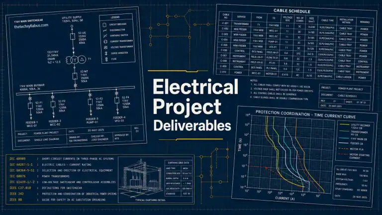
An SLD is a simplified diagram showing the power flow from source to loads. Must include: all switchgear ratings (voltage, kA), transformer ratings, generator details, cable sizes and lengths, CT/PT ratios, relay designations, earthing scheme, and load details. It's the primary design document.
The three-line diagram shows all three phases, CT and VT connections, and wiring to relays and meters. It includes current and voltage circuit details, essential for protection design and commissioning. It expands each SLD symbol into its three-phase representation.
Cable schedule lists each cable with: cable number, type, size, number of cores, source and destination, routing, estimated length, voltage drop, and gland type. Used for procurement, installation, and testing.
Start with power circuit (contactor, overload relay, breaker). Then control circuit: start/stop push buttons, remote/local selector, interlocks (e.g., limit switches). For star-delta, include timer and interlocking contactors. For VFD, the drive provides its own control; external commands via hardwired or fieldbus. Schematic follows IEC 60947-4-1 for motor starters.
CTs step down current for measurement and protection; their secondary (1A/5A) connects to relays. VTs step down voltage for metering and protection. The schematic shows star/delta connections, earthing, and burden calculations. Correct polarity is critical for differential and directional relays.
A feeder pillar is a low voltage distribution enclosure containing busbars, MCCBs, and cable terminations for multiple motor/lighting feeders. Design ensures adequate IP rating, busbar rating, spare capacity, and easy access for maintenance. Typically outdoor type IP65, with bottom cable entry.
Interlocks prevent unsafe or conflicting operations. Electrical interlocking uses contacts in series (e.g., two contactors not both closed). Mechanical interlocks prevent simultaneous racking of two breakers (bus coupler/incomer). Also used for safety: key interlock systems (Castell) to ensure correct sequence of operations.
A bus tie breaker connects two bus sections. Normally open, it can be closed to transfer load between transformers or during maintenance, enhancing flexibility and availability. Must be interlocked to prevent paralleling of sources that are not synchronized.
In SLD: two incoming feeders (utility and generator) with a transfer switch symbol (double-throw contactor or motorized breaker). In schematics: show control logic (voltage sensing relays, time delays, mechanical/electrical interlocks). ATS controller ensures only one source connected at a time.
Load flow (power flow) determines steady-state voltages, branch power flows, and losses under given generation and load. Outputs: bus voltages (p.u.), branch currents, real/reactive power flows, transformer tap positions, and equipment loading percentages. Used to validate system design before procurement.
Large motor starting can cause excessive voltage dip affecting other equipment. The study checks voltage drop at motor terminals and on common bus during starting. If excessive, solutions: reduced voltage starter (soft starter, VFD), capacitor assist, or separate transformer. Typically voltage dip must be < 15% at motor and < 10% at other loads.
Required when total non-linear load (VFDs, UPS, LED lighting) exceeds 15–25% of transformer capacity. The study models harmonic sources, calculates voltage and current distortion (THD) at buses, and checks compliance with IEEE 519 or IEC 61000-3-6. Mitigation: passive/hybrid filters, 12-pulse drives, or active front-end.
Transient stability assesses the power system's ability to maintain synchronism after a large disturbance (fault, loss of generation). It evaluates critical clearing time and determines if generators remain stable. Important for industrial plants with own generation synchronized to grid.
Short-circuit study calculates bolted fault currents for equipment rating. Arc flash study (IEEE 1584) calculates incident energy from arcing faults, considering arc gap, enclosure type, and clearing time. It determines PPE requirements and arc flash boundary. Both use the same system model.
Measures voltage sags/swells, harmonics, flicker, transients, and unbalance at various points. Uses power quality analyzers (Fluke 435, Dranetz). Helps identify the source of disturbances and design mitigation (filters, voltage stabilizers). Often performed before adding sensitive equipment.
ETAP (or SKM PowerTools, DigSilent) is used for system modeling, load flow, short-circuit, protection coordination, motor starting, harmonic, and arc flash studies. It ensures the design complies with standards, generates reports, and produces time-current coordination curves. It's integral to the design process in EPC projects.
A discrimination study ensures that only the protective device nearest to the fault operates. Validated by plotting TCC curves of all series devices (relay, breaker, fuse) and checking time margins (typically 0.2–0.4 sec). For LV, manufacturers provide cascading tables verified by type testing.
Relay coordination sets pickup and time delays for overcurrent relays in a radial system. Typical feeder relay: pickup 1.05–1.25 FLC, time delay 0.2–0.4 sec above downstream. Instantaneous element set above maximum inrush and downstream fault, but below minimum bus fault.
IEEE C37.010 specifies that MV breakers are tested at X/R = 17. If the system X/R is higher, the asymmetrical current is greater, and the breaker's interrupting capability must be derated. This ensures the breaker can handle the actual DC offset. Similar for LV, tested at X/R = 14.
IEC uses metric units, 50Hz primary (but also 60Hz), SI system. IEEE/ANSI uses US customary units, 60Hz. Equipment symbols, circuit designations, and test procedures differ. In international projects, the client specifies the standard to follow. The engineer must be familiar with both.
The electrical equipment list itemizes all major electrical items (motors, transformers, switchgear, panels, UPS) with ratings and tag numbers. It feeds into the instrument index for instruments associated with those equipments (e.g., motor winding temperature, transformer Buchholz relay). Both are part of the project master document register.
Cable tray fill ratio per NEC Article 392: max 50% fill for power cables, 40% for control cables, but engineering practice often limits to 40% initial with 25% spare. Calculate total cross-sectional area of cables and compare with tray internal area. Also consider weight loading and bending radius.
A load schedule summarizes all connected loads with their kW, kVAR, kVA, demand, and diversity factors to determine total system load. A panel schedule details the loads fed from a specific distribution panel, showing circuit breaker sizes and phase balancing. The load schedule feeds into the panel schedules.
The DBM defines the design philosophy, applicable standards, voltage levels, equipment specifications, environmental conditions, system configuration, and assumptions. It is the foundational document approved by the client before detailed design begins.
Include: type (fixed/draw-out), rated voltage, rated current, short-circuit rating (Icw, Ipk), internal arc class, IP rating, busbar details, paint specification, type tests references, and required certifications. Also specify accessories: digital meters, protection relays, communication interface.
Review vendor drawings (GA, schematics, data sheets) to ensure compliance with project specification, interface compatibility (e.g., CT ratios, communication protocol), and integration with overall system design. Identify any deviations and resolve them before manufacturing.
Specify IEDs with IEC 61850 communication, define logical nodes and GOOSE messaging for fast protection interactions, and use station bus architecture. Design the network (PRP/HSR) for redundancy. The SAS (substation automation system) architecture must match the SCD (Substation Configuration Description) file per IEC 61850-6.