Power Cable Installation Sequence and Arrangement: How to Lay Single Core Cables the Right Way
If you have worked on any site, you know this scene. The cable drum is ready, the trench is open, the labourers are waiting. Then someone asks, “Sir, which cable goes where?”
This is a small question, but the answer matters a lot. When we run single core cables in parallel, the way we arrange them decides if all cables share the current equally or not. A wrong arrangement can make one cable hot while the others are sleeping. In this article, I will explain the arrangement and sequence in simple words, step by step, with the common layouts for 6, 9 and 12 single core cables.
Why Do We Use Parallel Single Core Cables?
When the load current is very high (for example, a big transformer feeding an LV panel), one cable per phase is not enough. A single huge cable becomes too thick, too heavy and difficult to bend. So we use two, three or four smaller cables per phase and connect them in parallel.
The idea sounds easy: more cables, more current capacity. But there is a catch. Single core cables carry AC current, and every cable creates a magnetic field around it. These fields affect the neighbouring cables. Because of this, the current does not always divide equally among the parallel cables.
Simple example: Think of four lanes on a road, but all the cars rush into one lane. That lane gets jammed while the other three are empty. Wrong cable arrangement does the same with current.
Basic Terms You Should Know
- R, S, T are the three phases. (Some people call them L1, L2, L3.) In the diagrams below, R is red, S is blue and T is black.
- N is the neutral conductor, shown in green in the diagrams.
- D is the outer diameter of one cable. We use it to measure the spacing between cable groups.
- Flat formation means cables are laid side by side in a row.
- Clover (trefoil) formation means three cables touch each other in a triangle shape.
The Golden Rules (Before We See the Diagrams)
- Use the same cable for all parallel runs. Same size, same material, same type, same length. Even a small length difference changes the current sharing.
- Keep the arrangement symmetrical. The layout should look the same from the left side and from the right side.
- Do not repeat the same sequence every time. In many layouts, we reverse the phase order in the next group. This balances the magnetic effect.
- Keep proper gaps. Groups are separated by at least 2D, and in multi-row layouts rows are kept at least 300 mm apart, as shown in the figures.
- Follow the same route for all cables. Do not send one cable through a hot area and another through a cool one.
Arrangement for 6 Single Core Cables
This is the case of two parallel sets of a three phase four wire system (R, S, T and N, two times).
1. Flat on the ground, one row
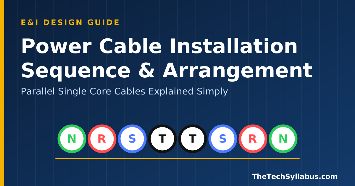
N1RSTTSRN2
Sequence: N1 – R – S – T – T – S – R – N2
See how the sequence is a mirror image. Starting from the centre, both sides are the same: T, S, R, N. This is the main trick. The two neutrals are at the outer ends, and the phases are mirrored in the middle.
2. Two rows, four cables each
N1RST
N2TSR
Top row: N1 R S T | Bottom row: N2 T S R (reversed)
Here the second row has the phase order reversed. The top row goes R-S-T and the bottom row goes T-S-R. This is a very common way to improve current sharing.
3. Clover shaped, in a row
N1RSSRN2TT
Clover arrangement with neutrals on the two outer ends
In this layout, the cables are grouped in a triangle so that they take less width. It is useful when the trench or tray is narrow. Notice that the T cables sit on top, and the neutrals stay on the outside.
Arrangement for 9 Single Core Cables
Now we have three parallel sets. Each set has R, S, T and N.
4. Flat on the ground, three groups
RSTN1
TSRN2
RSTN3
Groups are separated by a gap of at least 2D. The middle group has reversed phase order.
Each group of four cables is laid together, and then we leave a gap of at least 2D (twice the cable diameter) before the next group. The middle group runs in reverse order, T-S-R-N.
5. Three rows, one above the other
RSTN1
≥ 300 mm
TSRN2
≥ 300 mm
RSTN3
Three rows on separate trays, at least 300 mm apart
This is the cable tray style. Each tray carries one complete set. Again, the middle tray has the reversed order.
6. Clover shaped, three groups
RSN1TRSN2TRSN3T
Each clover group is kept ≥ 2D away from the next one
Arrangement for 12 Single Core Cables
For four parallel sets, the same logic continues. The layout is bigger, but the rules are the same: mirror the sequence, keep neutrals on the outside of each set, and keep the spacing.
7. Flat on the ground
N1RSTTSRN2
N3RSTTSRN4
Two mirrored blocks of 8 cables placed one after the other
8. Two rows in a tray
N1RSTTSRN2
≥ 300 mm
N3RSTTSRN4
Two rows, same mirrored sequence, 300 mm apart
9. Clover shaped, 12 cables
N1RSSRN2N3RSSRN4TTTT
Clover shape repeated for the second pair of sets
Quick Comparison
| Layout | Good Point | Watch Out |
|---|
| Flat, one row | Easy to lay and to inspect | Needs more trench width |
| Multiple rows (trays) | Good heat dissipation if spacing is kept | Need strong support and 300 mm gap |
| Clover shape | Saves width, compact | Heat can build up, so derating must be checked |
Common Mistakes I See on Site
- Same sequence everywhere. Laying R-S-T-N in every group without thinking about the mirror order.
- Different lengths. One cable is cut longer “just to be safe”. This creates uneven current.
- Cables touching when they should have a gap. The 2D rule is forgotten, and the cables heat each other.
- Wrong tagging. Phase tags are missed, and at termination people connect the wrong cable to the wrong bus.
- No cleats or ties for clover groups. During a short circuit, single core cables push each other with a big force. Without proper cleats, the formation can break.
Practical Site Checklist
- Check the approved drawing and the cable schedule first.
- Confirm all parallel cables are of the same size, type and length.
- Mark R, S, T and N at both ends before pulling.
- Lay the cables as per the sequence in the drawing. If the drawing shows reversed order, follow it exactly.
- Keep the gaps (2D between groups, 300 mm between rows) wherever the drawing says so.
- Install cleats or ties at proper intervals, especially for clover formation.
- Do continuity and insulation resistance tests before energizing.
- Check phase sequence at the termination before final connection.
Important: The diagrams in this article are for understanding the concept. For your real project, always follow the cable manufacturer’s recommendation, the approved design, the relevant IEC standard (like IEC 60364-5-52 for current carrying capacity and arrangement) and your local code. Derating factors for grouping and installation method must always be calculated by the design engineer.
Final Words
Cable arrangement looks like a small site detail, but it affects heat, current sharing and the life of your cable. The simple idea to remember is this: keep it symmetrical, mirror the phase sequence, keep neutrals outside, and maintain the spacing.
If you follow these four points, you will avoid most of the problems that come with parallel single core cables. Share this article with your site team, because they are the ones who will actually lay the cables.
Have a question about cable sizing or derating? Write it in the comments and I will try to cover it in a future article.